Before replacing any items please go through the following checklist
If your motor is making a clicking sound this is the safety clutch in the motor preventing damage to the motor.
This is not the gear box.
When clutch noise occurs, release the power switch.
Failure to do so will result in damage to motor and possibly other system components.
Your trailer legs should be cleaned and checked for debris on a regular basis.
Sand and dirt will cause legs to bind.
To clean landing gear legs
Extend landing legs as far as possible, clean drop tube and inner ram tube.
Coat exposed surface of tubes with silicone spray lubricant.
Coat inside of handle alignment tube with silicone spray lubricant.
Oil shaft bushing in gear box and leg gear heads with SAE 30 oil.
Lubricate gears in gear box and landing leg gear heads with extreme pressure grease.
*Do NOT open motor to lubricate as this voids warranty.
Any damage to the legs such a bending or denting will cause binding.
Check that your batteries and power supplies are at full levels to prevent damage to the motor.
Check wiring connections at battery. Clean terminals with a solution of baking soda and water.
Cover with a thin coat of grease.
Check wiring harness fuse, if blown replace with appropriate fuse.
Do not exceed weight limit of landing gear system
Do not use the landings legs to lift the trailer during tire changes, axle work or trailer servicing (the trailer weight will exceed the capacity of the landing legs).
The landing legs are designed to stabilize a portion of the trailer’s weight.
Support the front end of the trailer with structural stands rated for the GVWR of the trailer.
Grease Landing Gear Legs
You will want to remove the top of the leg and run the lube down on the sides to flush out any debris.
SAFETY WARNING:
• Read, understand and follow all instructions before installing and using product.
• NEVER allow anyone unfamiliar with the operating instructions to use this product.
• Failure to follow these warnings and instructions can result in property damage and/or serious bodily injury.
• Class A Customs is not responsible for improper installation, use, or maintenance of this product.
The following items must be done before operating the levelers.
• Warn all persons to stand clear of vehicle.
• Keep hands and clothing away from moving parts.
• Park the vehicle on a reasonably level site. Check for rocks, holes, or other obstructions.
• Soft/spongy ground may allow levelers to sink. Levelers must be on firm solid ground or surface prior to operation.
• Insure area below and around leveler is clear of obstructions.
• Do not extend the slide-outs until coach is level.
• Never exceed rated capacity of landing legs.
• Do not use the landings legs to lift the trailer during tire changes, axle work or trailer servicing (the trailer weight will exceed the capacity of the landing legs). The landing legs are designed to stabilize a portion of the trailer’s weight. Support the front end of the trailer with structural stands rated for the GVWR of the trailer.
• Chock both sides of trailer wheels before operating landing legs.
• Both legs must touch the ground or the surface at the same time.
• Never drop the trailer off the hitch.
• Never attempt to lift or level without having both foot plates properly installed.
• When cranking jack or coupling trailer, secure trailer from rolling.
• These landing gear jacks are designed for vertical loading. Excessive side forces must be avoided.
• Never attempt to adjust the drop legs when the landing gear jacks are under load.
• Make certain the drop leg safety retaining pins are fully inserted through both sides of the inner tube and the drop leg tube before using the landing gear jacks.
• Owner or operator must never position any part of their body under any portion of the
jack or the load being supported or allow anyone else to be positioned under the load being supported. Disregard could cause property damage and/or serious bodily injury.
• Do not retract past the STOP label.
• Retract landing legs completely before towing trailer.
• Most switches are not ignition protected. DO NOT install these in areas which require ignition protected devices (such as battery or propane tank storage compartments). Only the Ignition Protected Switch is approved for installation in these compartments.
• Failure to follow these warnings and instructions can result in property damage and/or serious bodily injury.
POWER OPERATING INSTRUCTIONS
On a trailer equipped with a Venture Mfg. Co. 12VDC Power Kit follow the same procedures as “MANUAL OPERATING INSTRUCTIONS” except, operate the switch control to EXT (extend) or RET (retract) as indicated.
Power Kit is equipped with an overload clutch and a 30 AMP fuse. If fuse blows during normal operation replace fuse (located on the pink wire) with standard 30 AMP AGC type fuse.
Verify battery is fully charged before attempting further operation.
If clutch slips it may indicate you have reached the extend or retract limits of the jacks OR the trailer weight has exceeded the max rated load of the Landing Gear system.
Items stored inside/on the trailer can greatly affect the weight applied to Landing Gear system. If clutch consistently slips during normal operation, redistribute items stored in the trailer.
• When clutch noise occurs, release the switch. Failure to do so may also destroy
the clutch, in which case the entire power kit will have to be replaced.
• Potential damage to the trailer frame may occur if legs or power kits are operated
unevenly. Front of trailer must remain horizontal.
MANUAL OPERATING INSTRUCTIONS
For manual operation of fifth wheel landing gear on a trailer not equipped with a 12 VDC power kit, or if power is not available, proceed as follows:
• Drop Leg Operation: Disengage drop leg safety retaining pin to lower or raise foot plate to desired position, return the safety retaining pin making sure it is fully inserted through both the inner tube and the drop leg tube before using the jack.
(1) Attach the manual crank handle and crank until the inner tube is halfway to the ground.
(2) Remove the safety retaining pin from the drop leg tube. Let the drop tube fall to the ground and re-pin in the nearest adjustment hole.
(3) Continue extending landing legs until pin box disengages from the hitch and the trailer’s weight is completely removed from the hitch.
(4) When there is sufficient clearance between the pin box and hitch, move tow vehicle clear of trailer. Never drop trailer off the hitch.
(5) Lower trailer until it is level.
(6) Remove and store crank handle.
• To Retract: Perform “To Extend” instructions in reverse. Be certain the landing gear legs are fully retracted; drop legs are re-pinned in the fully retracted position; and foot plate is higher than the lowest point of the trailer to prevent dragging. Remove and store the crank handle.
Class A Customs
1130 County Road 6 West
Elkhart, IN 46514
Call Us: (574) 206-0101
Roughly 32” Overall Retracted (top of Leg to Bottom of Leg - does not include adding foot pad)
Roughly 48" Long Fully Extended (top of Leg to Bottom of Leg - does not include adding foot pad)
Painted Black Section 29 ½” long x 2 ½” wide
Inner Leg Tube Roughly 2" wide (shaft for foot pad)
15 ½” Inner Edge to Inner Edge
17 ½” Outer Edge to Outer Edge
Single Motor System 2,500 lbs. per leg / 5,000 lbs. system
Dual Motor System 3,000 lbs. per leg / 6,000 lbs. system
Follow/Idle Leg Only Class A Customs Part # TSB-FL
Drive/Lead Leg Only Class A Customs Part TSB-DL
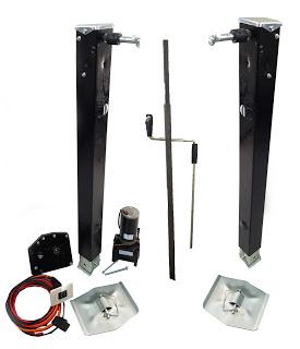
Class A Customs Part # TSB-2L1M1S
2 (Two) Landing Gear Leg (1 Lead/Drive and 1 Follow/Idle)
1 (One) Cross Bar
1 (One) 5th Wheel Landing Gear Motor
1 (One) Reduction Gear Box
1 (One) Wiring Harness w/ Switch
2 (Two) Foot pad
1 (One) Manual Crank Handle
NO Mounting Hardware
Class A Customs Part # TSB-2L1M1S
Cross Bar is used to hook Drive Leg to Idle Leg, Motor is hooked to Drive Leg and powers both legs. Larger units will need a Dual Powered System.
Do not exceed weight limit of landing gear system
Do not use the landings legs to lift the trailer during tire changes, axle work or trailer servicing (the trailer weight will exceed the capacity of the landing legs).
The landing legs are designed to stabilize a portion of the trailer’s weight.
Support the front end of the trailer with structural stands rated for the GVWR of the trailer.
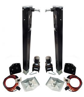
Class A Customs Part # TSB-2L2M2S
2 (Two) Landing Gear Leg (1 Lead/Drive and 1 Follow/Idle)
2 (Two) 5th Wheel Landing Gear Motor
2 (Two) Reduction Gear Box
2 (Two) Wiring Harness w/ Switch
2 (Two) Foot pad
NO Mounting Hardware
Class A Customs Part # TSB-2L2M2S
Larger units and units with larger amount of weight need a Dual Motor System.
Each motor must have a switch, you can use a dual switch that has two switches in one face plate but you can not one switch on two motors.
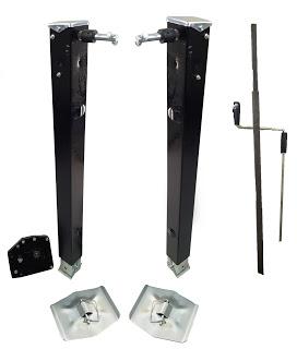
Class A Customs Part # TSB-C-2L
2 (Two) Landing Gear Leg
1 (One) Reduction Gear Box
1 (One) Cross Bar
2 (Two) Foot pad
NO Mounting Hardware
Class A Customs Part # TSB-C-2L


