These
instructions will help you operate and maintain your pump. This owner's
manual covers the EZ-8RV and EZ-8RVS, 12-volt electric gear pumps. This
manual covers models with manual nozzle.
These instructions will help you operate and maintain your pump. This owner's manual covers the EZ-8RV and EZ-8RVS, 12-volt electric gear pumps. This manual covers models with manual nozzle.
Notice: This pump is not intended to be used with an automatic nozzle.
An automatic bypass valve prevents pressure build up when the pump is on with the nozzle closed.
To avoid motor damage, do not run the pump more than 5 minutes with the nozzle closed.
The rated duty cycle of this pump is 15 minutes ON and 30 minutes OFF.
Allow the pump to cool for 30 minutes.
FUEL TYPE
This pump is designed for use only with gasoline (up to 15% alcohol blends such as E15), diesel fuel (up to 20% biodiesel blends such as B20) and kerosene.
Do not
use this pump for dispensing any fluids other than those for which it
was designed. To do so may damage pump components and will void the
warranty.
This pump is designed to operate on a typical 12-volt DC automotive electrical system.
The
pump is designed to operate with 12-volts DC at the motor leads and the
ratings are determined at this voltage. Performance may vary due to
length of power cord, battery condition or output from vehicle charging
system that will affect system voltage.
Do not leave the
system running without fluids. "Dry running" can damage the pump. If the
system fails to deliver fuel after 15 to 20 seconds, turn the system
off and refer to the Troubleshooting Section.
Do not pump the tank completely dry, as contaminants from the bottom of the tank may enter the pump.
SAFETY INSTRUCTIONS
Observe all safety precautions concerning safe handling of petroleum fuels.
To
ensure safe operation, all fuel transfer systems must be properly
grounded. Proper grounding means a continuous metal-to-metal contact
from one component to the next, including tank, bung, pump, meter,
filter, hose and nozzle.
Care should be taken to
ensure proper grounding during initial installation and after any
service or repair procedures. For your safety, please take a moment to
review the warnings in this manual.
To prevent physical injury, observe precautions against fire or explosion when dispensing fuel.
Do not
operate the system in the presence of any source of ignition including
running or hot engines, lighted cigarettes, or gas or electric heaters.
Observe precautions against electrical shock when operating the system.
Serious or fatal shock can result from operating electrical equipment in damp or wet locations.
Inspect
external pump wiring regularly to make sure it is correctly attached to
the battery. To avoid electrical shock, use extra care when connecting
the pump to power.
Avoid prolonged skin contact with petroleum
fuels. Use protective goggles, gloves, and aprons in case of splashing
or spills. Change saturated clothing and wash skin promptly with soap
and water.
Observe precautions against electrical shock when servicing the pump.
Always disconnect power before repairing or servicing.
Never apply electrical power to the system when any of the coverplates are removed.
INSTALLATION
This pump is designed to self-prime with dry gears.
Make
sure all threaded fuel connections are wrapped with three to four turns
of Teflon® tape or a pipe thread sealant approved for use with
petroleum fuels.
Clean the tank interior of all dirt and debris.
Make sure the tank is vented. A vent cap rated at 3 psi or less is recommended.
Suction line design and size is important for optimum pump performance. GPI requires suction line to be 3/8" miminum diameter.
Pump must be mounted within the clearance lines of the vehicle and protected from road impact damage.
A
grounding connection is provided. It is identified as a green colored
binding head screw in the electrical cavity. Connect these pumps only to
a 12-volt DC power source.
Do not attempt connection to a 24-volt DC, 115-volt AC or 230-volt AC power source.
For installation in unclassified areas, a flexible power cord, fuse and strain relief grip should be used.
NOTE: These components have not been evaluated
as part of the UL Listed Equipment and are not intended for use in a
Hazardous (Classified) Location.
To install the power cord, remove
the electrical coverplate. If necessary, trim the power cord to the
desired length. Strip 3 to 4 inches (7.5 to 10 cm) of outer insulation
from the power cord end. Then strip 1/2 in. (1.3 cm) of insulation from
the power cord wires. Slide the strain relief grip onto the power cord
so that the threaded end of the strain relief grip faces the stripped
power cord wires. Insert the power cord through the 1/2 inch NPT
connection on the back of the pump. Using wire nuts, connect black wire
to black and red wire to red in the pump's electrical cavity. Position
the wires inside the electrical cavity and tighten the strain relief
grip securely. Make sure surfaces are clean. Install the coverplate and
tighten securely.
!!! WARNING !!!
Carefully
route the power cord to the battery, protecting the power cord from hot
surfaces, sharp edges or anything that could damage the power cord,
resulting in a short circuit.
!!! WARNING !!!
Pump
must have circuit protection per ANSI/RVIA 12. A 20-amp slow-blow fuse
is a minimum requirement to protect the motor and power cord. Install
fuse in the red wire of the power cord adjacent to the battery. Connect
the fuse to the positive (ungrounded) side of battery. Connect black
wire to the negative (grounded) side of battery.
!!! DANGER !!!
If pump is to be installed in a Hazardous (Classified) location, it must
be installed by a licensed electrician and conform to National Fire
Protection Association (NFPA) codes 30 and 70. You as the owner, are
responsible for seeing that the installation and operation of your pump
complies with NFPA codes as well as any applicable state and local
codes. Rigid conduit must be used to install wiring. Note that the lead
wires are factory-sealed isolating the motor from the junction box.
Install Hose and Nozzle
After sealing threads, tighten the hose into the pump outlet and the
nozzle on the hose.
Failure to follow these wiring instructions may result in death or
serious injury from shock, fire or explosion.
OPERATION
ALWAYS FOLLOW SAFETY INSTRUCTIONS WHEN OPERATING THIS EQUIPMENT.
Before each use, repair leaks around seals or connections. Make sure hoses are in good condition and connections are tight.
MAKE SURE THE PUMP IS PROPERLY GROUNDED.
Repair
any corroded or damaged wiring before use. Ensure the tank contains
enough fuel. Make sure the fuel is not contaminated with debris.
To Dispense Fuel
Depending
on the model, turn pump on by activating the power circuit on the RV or
by lifting up on the switch lever. Insert the nozzle into the receiving
tank and squeeze the handle to start fuel flow. When done, release the
nozzle handle and turn off the pump.
This pump is designed to be self-priming. If fuel is not delivered
within 15 to 20 seconds, turn the pump off and refer to priming
information in the Troubleshooting Section.
An automatic
bypass valve prevents pressure build up when the pump is on with the
nozzle closed. To avoid pump damage, do not run the pump more than 5
minutes with the nozzle closed.
After running the pump for a maximum of 15 minutes, allow it to cool for
30 minutes.
Auxiliary Temperature-Limiting Device
The
motor is provided with an internal auxiliary temperature-limiting
device. Excessive motor heat can trip the device. It resets
automatically after the motor has cooled.
MAINTENANCE
This
pump is designed for minimum maintenance. Motor bearings are sealed
and require no lubrication. Inspect the pump and components regularly
for fuel leaks and make sure the hose and power cord are in good
condition. Keep the pump exterior clean to help identify leaks.
Do not
use this pump for water, chemicals or herbicides. Dispensing any fluid
other than that listed in this manual will damage the pump. Use of the
pump with unauthorized fluids will void the warranty.
The
EZ-8RV and EZ-8RVS Fuel Pumps are designed to safely transfer low
viscosity petroleum fuels such as gasoline (up to 15% alcohol blends
such as E15), diesel fuel (up to 20% biodiesel blends such as B20) and
kerosene.
Performance:
Pump Rate: Up to 8 GPM (30 LPM)
Duty Cycle: 15 min. ON, 30 min. OFF
Operating Temperature:
-20°F to + 125°F (-29°C to +52°C)
Operating Pressure:
15 PSI
Electrical Specifications:
Input 12-volt DC
Current Draw: 11 amp
Motor: 2100 RPM, UL Listed to UL and Canadian Standards
1/10 HP (75 watts)
Mechanical Connections:
Inlet 1 in. NPT Outlet 3/4 in. NPT
SERVICE
In the event the GPI pump fails, contact your RV dealer.
Owner's responsibilities:
1.
The warranty period shall begin on the date of the original purchase
of the RV. This warranty is transferable but does not extend the
original warranty period of 2 years.
2. Replacement pump
will be subject to and covered by GPl's standard warranty but does not
extend beyond the original warranty period of 2 years.
3.
The owner must establish these dates by presenting legible papers at
the time the warranty claim is made showing the purchase or installation
date.
4. Locate Owner's Manual and have available.
Dealer's responsibilities:
Before providing any warranty service the
RV Dealer must
1.
Determine that the pump is under warranty by checking either the
customer receipt or the Date of Manufacture on the pump. GPI EZ-8RV or
EZ-8RVS pumps have a two (2) year warranty period from either the Date
of Purchase or the Date of Manufacture.
2. Determine if
the pump has been modified with an automatic nozzle or a non-UL hose
assembly. The use of an automatic nozzle or a non-UL hose invalidates
the warranty.
3. Non-Warrantable failure are as follows:
• Damage from unauthorized repairs, misuse, abuse or neglect.
• Damage caused by accidents, overloading, or unauthor- ized alteration in any way.
• Acts of weather or corrosion of the housing.
• Damage due to theft, vandalism, fire or explosion.
• Improper installation, application and tampering of any portion of the RV fuel system.
• Use of unauthorized fluids, such as specified gasoline blends in excess of E-15, Bio-diesel blends in excess of B-20.
• Pump failure due to fuel contamination and blocked fuel lines.
• Using the EZ-8RV/EZ-8RVS for commercial purposes.
• Pump accessory failures, such as fuel hose assembly,nozzle, power cord and/or inlet fittings.
• Expenses relating to or arising out of transportation of the toy hauler to a designated dealer location.
4. If the pump is under warranty and the failure is warrantable:
•
Contact GPI for an RGA # (Returned Goods Authorization) and a call
tag for pick up of the defective pump. GPI Customer Service Telephone:
800-835-0113.
• Replace the defective RV Pump with the unit provided by GPI.
• Complete and have the customer sign the Warranty Claim Form (provided by GPI Customer Service).
• Return the completed Warranty Claim Form to GPI within 30 days.
• Provide Customer with a copy of the completed Warranty Claim Form for their records as Proof of Purchase.
Great
Plains Industries, Inc. 5252 E. 36th Street North, Wichita, KS USA
67220-3205, hereby provides a limited warranty against defects in
material and workmanship on all products manufactured by Great Plains
Industries, Inc. This product includes a 2 year warranty from date of
purchase as evidenced by the original sales receipt. A 30 month warranty
from product date of manufacture will apply in cases where the original
sales receipt is not available. Reference product labeling for the
warranty expiration date based on 30 months from date of manufacture.
Manufacturer's sole obligation under the foregoing warranties will be
limited to either, at Manufacturer's option, replacing or repairing
defective Goods (subject to limitations hereinafter provided) or
refunding the purchase price for such Goods theretofore paid by the
Buyer, and Buyer's exclusive remedy for breach of any such warranties
will be enforcement of such obligations of Manufacturer. The warranty
shall extend to the purchaser of this product and to any person to whom
such product is transferred during the warranty period.
This warranty shall not apply if:
A.
the product has been altered or modified outside the warrantor's duly
appointed representative;
B. the product has been subjected to neglect, misuse, abuse or damage
or has been installed or operated other than in accordance with the
manufacturer's operating instructions.
Water often can be made safe to drink by boiling, adding disinfectants, or filtering.
IMPORTANT: Water contaminated with fuel or toxic chemicals will not be made safe by boiling or disinfection. Use a different source of water if you know or suspect that water might be contaminated with fuel or toxic chemicals.
Boiling
If you don’t have safe bottled water, you should boil water to make it safe. Boiling is the surest method to make water safer to drink by killing disease-causing organisms, including viruses, bacteria, and parasites.
You can improve the flat taste of boiled water by pouring it from one container to another and then allowing it to stand for a few hours, OR by adding a pinch of salt for each quart or liter of boiled water.
If the water is cloudy,
Filter it through a clean cloth, paper towel, or coffee filter OR allow it to settle.
Draw off the clear water.
Bring the clear water to a rolling boil for one minute (at elevations above 6,500 feet, boil for three minutes).
Let the boiled water cool.
Store the boiled water in clean sanitized containers with tight covers.
If the water is clear,
Bring the clear water to a rolling boil for one minute (at elevations above 6,500 feet, boil for three minutes).
Let the boiled water cool.
Store the boiled water in clean sanitized containers with tight covers.
Disinfectants
If you don’t have safe bottled water and if boiling is not possible, you often can make water safer to drink by using a disinfectant such as unscented household chlorine bleach or iodine. These can kill most harmful organisms, such as viruses and bacteria, but are not as effective in controlling more resistant organisms such as the parasites Cryptosporidium and Giardia.
To disinfect water,
Filter it through a clean cloth, paper towel, or coffee filter OR allow it to settle.
Draw off the clear water.
To use bleach, add 1/8 teaspoon (or 8 drops; about 0.625 milliliters) of unscented liquid household chlorine (5-6%) bleach for each gallon of clear water (or 2 drops of bleach for each liter or each quart of water),
Stir the mixture well.
Let it stand for 30 minutes or longer before you use it.
Store the disinfected water in clean sanitized containers with tight covers.
To use iodine, follow the manufacturer’s instructions.
Chlorine dioxide tablets are another disinfectant that now is available in some outdoor stores. This disinfectant has proven to be effective against pathogens, including Cryptosporidium, if the manufacturer’s instructions are followed.
Filters
Many portable water filters can remove disease-causing parasites such as Cryptosporidium and Giardia from drinking water. If you are choosing a portable water filter, try to pick one that has a filter pore size small enough to remove both bacteria and parasites. Most portable water filters do not remove viruses.
Carefully read and follow the manufacturer’s instructions for the water filter you intent to use. After filtering, add a disinfectant such as iodine, chlorine, or chlorine dioxide to the filtered water to kill any viruses and remaining bacteria. For more information about water filters, see the Water Treatment Resources section.
Water Treatment Resources
To learn more about water filters and treatments that can remove microorganisms such as viruses, bacteria, and parasites (such as Cryptosporidium), see the following resources:
Class A Customs at this time does not ship outside of the US.
Free Shipping Items Standard Shipping to U.S. addresses in the 48 Contiguous U.S. only.
Orders are processed next business day. If you are needing to cancel an order please call to confirm, order will ship unless confirmation has been made.
Class A Customs list of currently manufactured Water Tanks can be found at the top of each webpage along with the Water Tank Form.
We can make a custom tank however you would need to pay for a mold ($3,000 - $8,000). For more information you can email a CAD drawing or spec sheet and a sales member will contact you.
UV-8 stabilization
Complies with:
U.S. FDA 21 CFR 177.1520 (c)3.1a
Canadian HPFB No Objection
Underwriters Laboratories Inc.
EU, 10/2011
NSF International NSF/ANSI Std 61 (sec 4 & 5)
You must verify requirements with health department where inspection will be made before purchasing.
Forward the documents provided to your local health department before purchasing to be sure these tanks will pass your local inspection, this is your responsibility.
Codes vary by local health departments, not states, we are not aware of the codes.
Fresh Water Tank
Size (Gallons / Measurements)
Fittings (Size / Placement / Materials)
Filling Procedure (Lockable Fill Dish / Materials)
Tank Placement (Inside / Outside)
Gray Water Tank
Size (Gallons / Measurements - Health Departments require the Gray tank to be larger than the Fresh)
Fittings (Size / Placement / Materials)
Drainage (Fittings / Placement)
Tank Placement (Inside / Outside)
Gray Water Tank Calculation
Multiply (fresh tank size) x 1.15 (1 . 15%) = Tank needed
30 x 1.15 (15%) = 34.50
30 x 1.50 (50%) = 45
I have only so much room how many gallons can I get in that space?
We do not recommend sizes or verbally give measurements please look at the Water Tank List located at the top of each webpage to see all tanks Class A Customs currently manufactures.
How are the water tanks measured?
Please be sure to look at the photos provided with each item as measurements and fitting placements will be included. Note the measurement of the tanks do not include the fittings, this will add extra length to the tank.
~ Fittings ~
Due to increased sales we are no longer
able to offer custom fittings on water tanks.
If you are a
manufacturer or OEM needing custom fittings please contact
sales for more information, minimum quantity of 50 tanks will apply.
Where are the fittings located in the tank? What kind of fitting are in the tank?
Our Stock Tanks come with 4 fittings all located on the same side of the tank. Be sure to look at the tank photos and description to clarify fittings.
Can I cut a hole in the tank and glue another fitting in?
No, fitting are spun welded into the tank, friction between the fitting and the tank causes both to melt and permanently seal, no additional glues or sealants are used to install the fittings.
The residue left by putting the fittings in place is part of the material the tanks and fittings are made from and may spider crack or flake off over time, this in no way harms the tank or causes any usage issues.
Is that a fitting or a clean-out on the side?
Each tank will come with at least one vent hole made during the manufacturing process, a permanently mounted patch is placed over this hole this is not a fitting and does not unscrew.
~ Plumbing ~
Have a certified technician install all parts to prevent product damage and personal injury.
All water tanks we carry must be vented, they are not pressurized tanks.
You must allow air to move in and out when filling and emptying the tank.
Do NOT fill the tank directly from a pressurized line (garden hose), this is not a safe option and will explode the tank. We recommend using a fill dish to allow for gravity feeding of the tank, please review our plumbing example for more information.
This will depend on how you are setting-up your tank and will vary by application. Please view our Plumbing Category for information on loose fittings we carry.
At this time Class A Customs only installs the following fittings into our Fresh / Gray tanks
.5" NPT Female
1.5" NPT Female
1.25" Outer Diameter x 2" Long Smooth Pipe (Boss Fitting)
It is recommended to use plastic male fittings with plastic female fittings to avoid damaging the threads, metal thread fittings can crush the plastic threads.
.5" fitting can be used for air vent and water pump
1.5" Fitting can be used for water inlet or drain
1.25" spout fitting can be used for water inlet or drain
What is a fill dish?
The fill dish is located on the outside of your unit so that you can easily add water to your tank without the need of opening a compartment or climbing under your unit. You can find the fill dishes in the Plumbing Category.
For adding water to the Water Tank you need a Gravity Fill Dish, the hose rests in the port it does not screw onto the port this allows you to place a garden hose into the Gravity Fill Dish port without making a sealed connection so the supply is not pressurized.
For using water directly from a garden hose you need a City Fill Dish, the hose makes a sealed connection and the water supply is pressurized, you can not hook this to your water tank and you do not need to go through your water pump.
We carry Gravity Fill Dishes, City Fill Dishes and Combo Fill Dishes that have both gravity and city, the benefit of having both is you can have a water tank of fresh water but if you go to a location that supplies pressurized water (campground - fair - etc.) you do not need to use your water tank supply of water you can simply use the water provided. Be sure to look at the provided example plumbing diagram for more reference.
But what if I only turn the garden hose on half way?
Customers who do this still explode the tank because you can not determine the pressure of the water flowing only the amount of water.
I am not using a fill dish how can I fill the tank?
We recommend you place a fitting in the tank that will allow you to rest the hose in to fill, not make a sealed connection, you can then cap this when not in use. You can use an elbow fitting to allow you the fill the tank to capacity, use an elbow with a screen secured over it to vent the tank.
Can I put a cap on and off of the tank?
If you are needing to use a fitting by adding and removing a cap, remember tank must be vented allowing air in/out during use, we recommend you place a fitting in the tank and a cap on that fitting in order to prevent damage to the tank fitting.
~ Monitor Panels & Water Tank Probes ~
Water Tank optional Installed Water Tank Probes, Loose probes are available for customer installation.
The tank looks like the side is bowed, is it safe?
Due to the manufacturing process all the tanks especially the larger in size will have a bowing to the walls, when the tank is filled the tank will expand out removing the inward bow, we recommend laying all tanks on a level surface (this can be angled) and bracing the tanks. For larger tanks it is recommended to brace all side walls with plywood or metal, we do not recommend using ratchet straps on the tanks alone as this is a large amount of weight on a thin strip and may cause cutting into the tank.
Tank Average Thickness
All tanks will vary on thickness but on average they are .219 or 7/32" thick.
Can I stack the water tanks on top of each other?
No, do not place anything on the tanks, if you need to stack the tanks you will need a weight bearing shelf between them.
Do I need to brace the water tank?
It is recommended to brace all side walls with plywood or metal, we do not recommend using ratchet straps on the tanks alone as this is a large amount of weight on a thin strip and may cause cutting into the tank.
Can I set the tank up on end?
Yes, you can place the tank on any side, you will need to brace the tank and run a food grade pipe or hose down inside to reach the bottom of the tank. For easier use fittings can be moved and additional fittings added. You will need to fill-out the tank form to show the placement and once confirmed your order will be processed the next business day.
Can I mount the tank under the trailer?
For those getting inspections you will need to verify with your local health department if you are allowed to place the tank outside of your unit. For all other applications we recommend having the tank sit on a level surface such as plywood or sheet metal then bracing it with bars or straps, it is helpful to fully enclose the tank to prevent damage from rocks and debris during travel. Be sure you check clearance to avoid having the tank removed on a speed bump or curb.
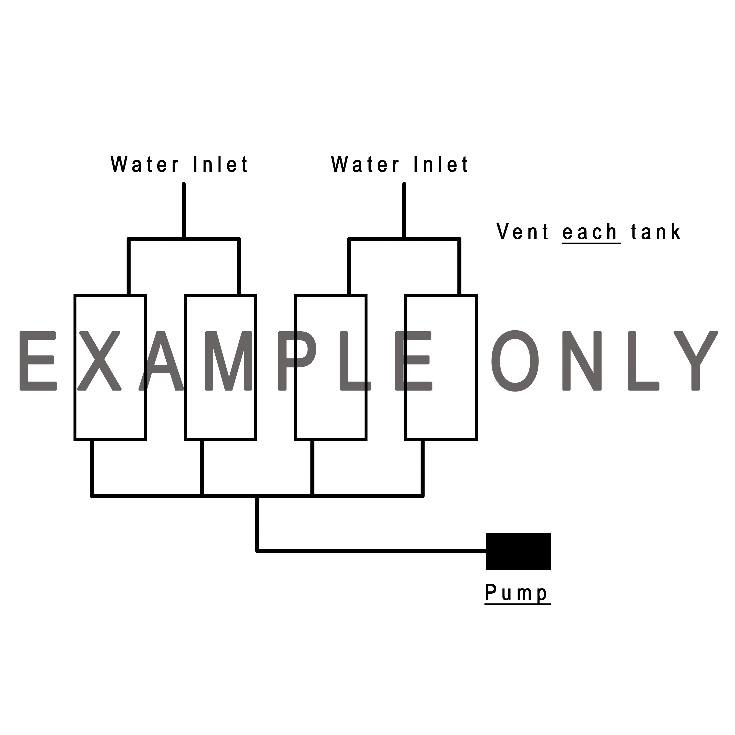
Can I hook more than one tank together?
Yes, you will need to check with a certified plumber to see what fittings and set-up will work best for your unit, remember to vent each tank.
This is an example only, installation will vary depending on your unit.
~ Sanitize Tank ~
When I get the tank what should I do first?
Sanitize each tank prior to use to remove any debris from the manufacturing process. Tanks are made in a warehouse so maybe dusty or scuffed, this does not effect the use or safety of the tank, wipe with a damp cloth to remove surface dust or scuffs.
1. Prepare a chlorine solution using one gallon of water and a ¼ cup of household bleach (5% sodium hypochlorite solution) ** DO NOT USE FRESH SCENT OR ANY SCENT ENHANCED BLEACH **
Never mix bleach with ammonia or other cleaners.
Open windows and doors to get fresh air when you use bleach.
With tank empty, pour chlorine solution into tank. Use one gallon of solution for each 15 gallons of tank capacity.
2. Complete filling of tank with fresh water.
3. Allow to stand for three (3) hours
4. Drain and flush with potable fresh water.
Any residual chlorine odor will dissipate naturally.
~ Waste Water Tank Help ~
Customer will measure and determine where inlet/vent will be placed on Black Waste Tank.
Use correct size hole saw bit in order to drill a hole in the tank and place rubber grommet in hole. Rubber grommet will secure inlet/vent pipe with no adhesives needed.
Included are a few short videos displaying the grommet installation process.
Customer will need to return all merchandise in new, unused condition and packing materials if available.
To return item customer will need to pay return shipping. Packages refused or return to sender will not be delivered back and no credit/refund will be issued.
Returns c/o Class A Customs
1130 County Road 6 West
Elkhart, IN 46514
Phone: 574-206-0101
Include a copy of original purchase receipt 20% Restock fee will be charged for all orders.
Return Process
This time period includes the transit time for us to receive your return from the shipper (5 to 10 business days), the time it takes us to process your return once we receive it (3 to 5 business days), and the time it takes to return the correct item. We'll notify you via e-mail of your refund once we've received and processed the returned item.