Showing posts with label Installation Instructions. Show all posts

Heng's 14-0129 SWITCH ONLY Vortex II Replacement circuit board Photo Instructions

Heng's Vortex I and Vortex II installation help with photos  1
2
3
4
5
6
7


8 When installing a Vortex Fan do not let the unit hang by the wires, damage will occur to the switch.
9
10
11
12 Vortex I and Vortex II are 12 volt power only
13
14 If you are not aware of your power supply please consult a certified electrician before ordering/installing.
15
16
17
18
19
20
21
22
23
24
25
26
27
28
29
30
31 NOTE: 
32
33 Vortex New Design has a pre-stamped cut-out for a fuse that is required in Canada.
34
35 This is not a defect in the housing but the new design by the manufacturer.
36
37
38
39
40
41 When installing a Vortex Fan do not let the unit hang by the wires, damage will occur to the switch.
42
43
44
45
46
47
48 1. Remove the handle from the vent.
49
50
51
Post settings Labels Vortex Vent, No matching suggestions Published on 1/6/21 11:34 AM Links Location Search Description Options

Replacing the vinyl trim on a pop-up camper

Replacing the vinyl trim on a pop-up camper - Post By http://www.campfiretravelers.com/

Stop over to their site to see photos and steps


Class A Customs
1130 County Road 6 West
Elkhart, IN 46514

Phone: (574) 206-0101

Half Moon Side Vent Cargo Trailer Air Vent 22813 classacustoms

A 3" hole will need to be cut in wall where you wish to place the inner vent piece.
Do not cut wall stud.

The 1/2 moon goes on the outside of your trailer matching up to the round part so the flat side of the 1/2 moon faces your trailer. These can be screwed or riveted on.

To promote airflow throughout trailer install one complete moon vent in upper front corner of trailer and additional moon vent in lower back corner or trailer, see diagram from examples.


Class A Customs
1130 County Road 6 West
Elkhart, IN 46514
 
Call Us: (574) 206-0101


Atwood Power Converter Charger Installation Instructions classAcustoms


 Atwood Power Converter Charger Installation Instructions classAcustoms


Class A Customs
1130 County Road 6 West
Elkhart, IN 46514
 
Call Us: (574) 206-0101


Heng's Part # 46128 - 1 Gallon Rubber Roof Coating Sealant Acrylic Latex Polymer classacustoms

1 Gallon Rubber Roof Coating Sealant Acrylic Latex Polymer Hengs Part #  46128 classacustoms


1 Gallon Rubber Roof Coating Sealant Acrylic Latex Polymer Hengs Part #  46128 classacustoms


1 Gallon Rubber Roof Coating Sealant Acrylic Latex Polymer Hengs Part #  46128 classacustoms


1 Gallon Rubber Roof Coating Sealant Acrylic Latex Polymer Hengs Part #  46128 classacustoms


Heng's Part #  46128 - 1 Gallon Rubber Roof Coating Sealant Acrylic Latex Polymer  classacustoms


Features:
100% Acrylic Latex Polymer
NO PRIMER NEEDED
COLOR White
COVERAGE up-to 200 sq. feet of surface area per gallon* (Your Unit Feet Length x Feet Height = Feet Squared)
APPLICATION Can be applied over galvanized steel, bituminous built-up roofs( BUR's), concrete, wood polyurethane foam and asphalt roof shingles or whatever a flexible, durable and long lasting protection is needed. Can be applied by brush, roller, or spray applicator. Equipment cleans easily with water (must be cleaned before coating hardens)
DESIGNED for elastomeric roof mastic and provides an excellent weatherproofing barrier against wind, rain, snow and sand.
RESISTS cracking and chipping due to it's low temp flexibility.
RESISTS UV rays and will expand/contract with the roof base.
REDUCES temperature, thereby reducing air conditioning costs.
This product complies with the California Clean Air Act.


SURFACE PREPARATION It is extremely important to get the roof clean and dry. First remove heavy deposits of dirt, leaves and other debris from the roof using broom or air broomer, then inspect the entire surface for any open seams, tears, cuts, etc. Repair these flaws so water is not blown in under membrane during the cleaning process. Pressure wash roof with water and allow to dry completely. DO NOT APPLY this coating at temperatures below 50deg F (10deg C), in high humidity or potential heavy dew conditions.
Biological Control: Areas of algae, mildew or fungus on the roof membrane or the existing coating
should be treated with a solution of 1 part household bleach and 3 parts water, followed by a power washer rinse using clear water. 
DRY TIME 1 1/2 hours drying time. 4 hours for second coat. and 24 hours to cure.
DO NOT Allow this item to Freeze in the container

This product complies with the California Clean Air Act.


Class A Customs
1130 County Road 6 West
Elkhart, IN 46514
 
Call Us: (574) 206-0101


5th Wheel TRIPOD Stabilizer King Pin jack support rv Heng's HG-80001 classacustoms

NOW IN STOCK


3,500 lb. 5th Wheel Tripod Stabilizer King Pin Jack by Heng's HG-80001 


Class A Customs
1130 County Road 6 West
Elkhart, IN 46514

Phone: (574) 206-0101

20" Ventless Range Hoods by Ventline - Installation Instructions

20" Range Hood 12V in STAINLESS STEEL Sloped Nose w/ Fan and Light DUCTLESS STYLE Part# 20-SSR12-DL

Features:


  • 12 volt: You can not put this in a house or plug into a wall - 110/115/220 volt will damage the unit.
  • 300 series 22 gauge stainless steel
  • Underside Light helps you to see while cooking.
  • 6" Fan helps move air
  • Two front panel rocker switches for separate control of the light and fan.
  • 12 volt Motor Included
  • 6" Fan Blade Included
  • 10W Light Bulb Included (do not use larger than 10W you will melt the light cover)
  • Frosted Plastic Light Cover Included
  • Washable filter is included.


  • Specifications:


  • 12 volt: You can not put this in a house or plug into a wall - 110/115/220 volt will damage the unit.
  • The overall size of this unit is 20" wide x 18" deep x 5 1/4" tall.
  • The slope nose allows installation of this unit with cabinets from 12"-18" deep.


  • PLEASE NOTE:
    These are 12 volt Range Hoods
    You CAN NOT use them in a house, that is 110 volt and will damage the unit.


    Range Hood Install Video

    Menard's Range Hood Video


    20" Ventless Range Hoods by Ventline - Installation Instructions

    Class A Customs
    1130 County Road 6 West
    Elkhart, IN 46514
     
    Call Us: (574) 206-0101

    How to install a Complete 5th Wheel Landing Gear Leg Set System - Legs, Cross Bar, Motor, Handle, Switch, Brackets, Foot Pad and more classAcustoms

    Before replacing any items please go through the following checklist

    If your motor is making a clicking sound this is the safety clutch in the motor preventing damage to the motor.
    This is not the gear box.
    When clutch noise occurs, release the power switch.
    Failure to do so will result in damage to motor and possibly other system components.

    Check for binding
    Your trailer legs should be cleaned and checked for debris on a regular basis.
    Sand and dirt will cause legs to bind.

    To clean landing gear legs
    Extend landing legs as far as possible, clean drop tube and inner ram tube.
    Coat exposed surface of tubes with silicone spray lubricant.
    Coat inside of handle alignment tube with silicone spray lubricant.
    Oil shaft bushing in gear box and leg gear heads with SAE 30 oil.
    Lubricate gears in gear box and landing leg gear heads with extreme pressure grease.
    *Do NOT open motor to lubricate as this voids warranty.

    Check for damage to legs
    Any damage to the legs such a bending or denting will cause binding.

    Check power to system
    Check that your batteries and power supplies are at full levels to prevent damage to the motor.
    Check wiring connections at battery. Clean terminals with a solution of baking soda and water.
    Cover with a thin coat of grease.
    Check wiring harness fuse, if blown replace with appropriate fuse.

    Do not exceed weight limit of landing gear system
    Do not use the landings legs to lift the trailer during tire changes, axle work or trailer servicing (the trailer weight will exceed the capacity of the landing legs).
    The landing legs are designed to stabilize a portion of the trailer’s weight.
    Support the front end of the trailer with structural stands rated for the GVWR of the trailer.

    Grease Landing Gear Legs

    You will want to remove the top of the leg and run the lube down on the sides to flush out any debris.


    SAFETY WARNING:
    • Read, understand and follow all instructions before installing and using product.
    • NEVER allow anyone unfamiliar with the operating instructions to use this product.
    • Failure to follow these warnings and instructions can result in property damage and/or serious bodily injury.
    • Class A Customs is not responsible for improper installation, use, or maintenance of this product.


    The following items must be done before operating the levelers.
    • Warn all persons to stand clear of vehicle.
    • Keep hands and clothing away from moving parts.
    • Park the vehicle on a reasonably level site. Check for rocks, holes, or other obstructions.
    • Soft/spongy ground may allow levelers to sink. Levelers must be on firm solid ground or surface prior to operation.
    • Insure area below and around leveler is clear of obstructions.
    • Do not extend the slide-outs until coach is level.

    • Never exceed rated capacity of landing legs.
    • Do not use the landings legs to lift the trailer during tire changes, axle work or trailer servicing (the trailer weight will exceed the capacity of the landing legs). The landing legs are designed to stabilize a portion of the trailer’s weight. Support the front end of the trailer with structural stands rated for the GVWR of the trailer.
    • Chock both sides of trailer wheels before operating landing legs.
    • Both legs must touch the ground or the surface at the same time.
    • Never drop the trailer off the hitch.
    • Never attempt to lift or level without having both foot plates properly installed.
    • When cranking jack or coupling trailer, secure trailer from rolling.
    • These landing gear jacks are designed for vertical loading. Excessive side forces must be avoided.
    • Never attempt to adjust the drop legs when the landing gear jacks are under load.
    • Make certain the drop leg safety retaining pins are fully inserted through both sides of the inner tube and the drop leg tube before using the landing gear jacks.
    • Owner or operator must never position any part of their body under any portion of the
    jack or the load being supported or allow anyone else to be positioned under the load being supported. Disregard could cause property damage and/or serious bodily injury.
    • Do not retract past the STOP label.
    • Retract landing legs completely before towing trailer.


    • Most switches are not ignition protected. DO NOT install these in areas which require ignition protected devices (such as battery or propane tank storage compartments). Only the Ignition Protected Switch is approved for installation in these compartments.

    • Failure to follow these warnings and instructions can result in property damage and/or serious bodily injury.


    POWER OPERATING INSTRUCTIONS
    On a trailer equipped with a Venture Mfg. Co. 12VDC Power Kit follow the same procedures as “MANUAL OPERATING INSTRUCTIONS” except, operate the switch control to EXT (extend) or RET (retract) as indicated.

    Power Kit is equipped with an overload clutch and a 30 AMP fuse. If fuse blows during normal operation replace fuse (located on the pink wire) with standard 30 AMP AGC type fuse.

    Verify battery is fully charged before attempting further operation.

    If clutch slips it may indicate you have reached the extend or retract limits of the jacks OR the trailer weight has exceeded the max rated load of the Landing Gear system.
    Items stored inside/on the trailer can greatly affect the weight applied to Landing Gear system. If clutch consistently slips during normal operation, redistribute items stored in the trailer.

    CAUTION
    • When clutch noise occurs, release the switch. Failure to do so may also destroy
    the clutch, in which case the entire power kit will have to be replaced.

    • Potential damage to the trailer frame may occur if legs or power kits are operated
    unevenly. Front of trailer must remain horizontal.

    MANUAL OPERATING INSTRUCTIONS
    For manual operation of fifth wheel landing gear on a trailer not equipped with a 12 VDC power kit, or if power is not available, proceed as follows:

    • Drop Leg Operation: Disengage drop leg safety retaining pin to lower or raise foot plate to desired position, return the safety retaining pin making sure it is fully inserted through both the inner tube and the drop leg tube before using the jack.

    • To Extend:
    (1) Attach the manual crank handle and crank until the inner tube is halfway to the ground.
    (2) Remove the safety retaining pin from the drop leg tube. Let the drop tube fall to the ground and re-pin in the nearest adjustment hole.
    (3) Continue extending landing legs until pin box disengages from the hitch and the trailer’s weight is completely removed from the hitch.
    (4) When there is sufficient clearance between the pin box and hitch, move tow vehicle clear of trailer. Never drop trailer off the hitch.
    (5) Lower trailer until it is level.
    (6) Remove and store crank handle.

    • To Retract: Perform “To Extend” instructions in reverse. Be certain the landing gear legs are fully retracted; drop legs are re-pinned in the fully retracted position; and foot plate is higher than the lowest point of the trailer to prevent dragging. Remove and store the crank handle.


    Class A Customs
    1130 County Road 6 West
    Elkhart, IN 46514
     
    Call Us: (574) 206-0101


    Overall Leg Dimension
    Roughly 32” Overall Retracted (top of Leg to Bottom of Leg - does not include adding foot pad)
    Roughly 48" Long Fully Extended (top of Leg to Bottom of Leg - does not include adding foot pad)

    Painted Black Section 29 ½” long x 2 ½” wide
    Inner Leg Tube Roughly 2" wide (shaft for foot pad)

    Tabs Distance
    15 ½” Inner Edge to Inner Edge
    17 ½” Outer Edge to Outer Edge

    NO Mounting Hardware

    Do Not Exceed Capacity
    Single Motor System 2,500 lbs. per leg / 5,000 lbs. system
    Dual Motor System 3,000 lbs. per leg / 6,000 lbs. system


    Follow/Idle Leg Only Class A Customs Part # TSB-FL


    Drive/Lead Leg Only Class A Customs Part TSB-DL


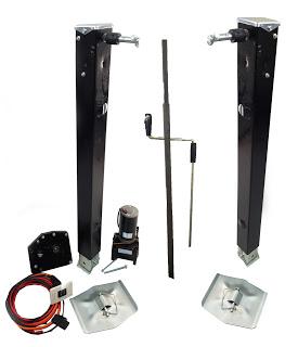
    Class A Customs Part # TSB-2L1M1S

    2 (Two) Landing Gear Leg (1 Lead/Drive and 1 Follow/Idle)
    1 (One) Cross Bar
    1 (One) 5th Wheel Landing Gear Motor
    1 (One) Reduction Gear Box
    1 (One) Wiring Harness w/ Switch
    2 (Two) Foot pad
    1 (One) Manual Crank Handle
    NO Mounting Hardware
    Class A Customs Part # TSB-2L1M1S

    Cross Bar is used to hook Drive Leg to Idle Leg, Motor is hooked to Drive Leg and powers both legs. Larger units will need a Dual Powered System.

    Do not exceed weight limit of landing gear system
    Do not use the landings legs to lift the trailer during tire changes, axle work or trailer servicing (the trailer weight will exceed the capacity of the landing legs).
    The landing legs are designed to stabilize a portion of the trailer’s weight.
    Support the front end of the trailer with structural stands rated for the GVWR of the trailer.


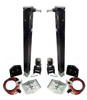
    Class A Customs Part # TSB-2L2M2S
    2 (Two) Landing Gear Leg (1 Lead/Drive and 1 Follow/Idle)
    2 (Two) 5th Wheel Landing Gear Motor
    2 (Two) Reduction Gear Box
    2 (Two) Wiring Harness w/ Switch
    2 (Two) Foot pad
    NO Mounting Hardware
    Class A Customs Part # TSB-2L2M2S

    Larger units and units with larger amount of weight need a Dual Motor System.
    Each motor must have a switch, you can use a dual switch that has two switches in one face plate but you can not one switch on two motors.


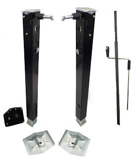
    Class A Customs Part # TSB-C-2L


    2 (Two) Landing Gear Leg
    1 (One) Reduction Gear Box
    1 (One) Cross Bar
    2 (Two) Foot pad
    NO Mounting Hardware
    Class A Customs Part # TSB-C-2L


    Manual Crank


    How does the reduction gear box go on? And will your box fit the unit I already have?

    If your motor does not look like our motor it will not work with your current system. You may need a new reduction gear box and rebuild kit. To find if your legs have the same gears inside you would need to open the leg to compare.


    This rebuild kit is for repairing the drive leg on 5th wheel landing gear
    This kit is also used to convert an idle leg into a drive leg for a dual motor system
    16T Bevel Gear
    12T Bevel Gear
    Lead Drive Shaft
    Drive Shaft Bushings
    E-Clip
    Spirol Pin
    Follow Drive Shaft
    Drive Pin
    Shim Washer
    Diagram in pictures shows all included parts.

    The hardest part of installing this kit is working in tight spaces. Your best route is to drop the leg out by unbolting the two bolts that hold the leg in. Once out it is a lot easier to work on and when your done you lift the leg back up and bolt it back in.


    Your leg needs to have a 1/2 moon shaft to fit our reduction gear box or you will need a rebuild kit.


    Be sure to place the black rubber stopper piece over the 1/2 moon shaft once you have the reduction gear box on the leg and use the screw provided to secure the stopper. 

    You do not screw the box to the leg the cross bar will keep the box mounted on.


     Again use the screw provided to secure the cross bar on to the 1/2 moon shaft.

     Secure the idle leg, there will be no rubber stopper on the idle leg.


     What if I am using a motor to make the legs powered how do I hook the motor up?


    The motor will attach to the reduction gear box and be secured with the two bolts provided. Be sure you correctly line the motor shaft with the crank shaft.


    If you already have the legs but need to change your motor(s) and gear box(es) your leg(s) needs to have a 1/2 moon shaft to fit our reduction gear box or you will need a rebuild kit.


    If you have a dual motor system you will need a rebuild kit, reduction gear box and motor for each leg. Due to different style motors if you have a different brand motor it is not advised to change just one motor at a time, the reason is the motors may lower/raise at different speeds causing damage to your trailer.


    If you lose power you can manually crank a system with a motor attached.


    I already have a motor can I buy one of your motors and use it with mine?

    If you have a Venture M-9000 (M PK-9000) Motor then yes.

    If you have an off brand or an ADTH motor then no. ADTH and other brands copied the Venture motor and most used plastic gears which wear down very easily. The motor speeds and different type of materials make them an unsafe match to use, you do not want one leg to go up or down faster than the other leg. This is the same problem with having a plastic gear box.


    Venture Landing Gear Motor M9000 / M-9000-PK


    REDUCTION GEAR BOX


    1/2 Moon Shaft


    3:1 gear ratio
    Will work with manual and electric systems.
    Cast Aluminum Casing
    Heavy Duty Cast Gears
    1/2 Moon Shaft


    Class A Customs
    1130 County Road 6 West
    Elkhart, IN 46514
     
    Call Us: (574) 206-0101